Terminal
Terminal connection
An identified electrical connection point linking schematic and wiring information.
Schematic
Terminals, conductors, cable systems, connections and earthing references. Explore 77 references, with original explanations and public primary sources.
An identified electrical connection point linking schematic and wiring information.
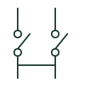
A current-transformer terminal arrangement providing documented test and shorting facilities.

An identified connection serving the protective earthing function.
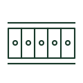
A physical assembly of identified terminals and the selected connecting accessories.
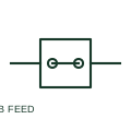
A feed-through terminal provides an electrical connection between conductors assigned to the same terminal path.
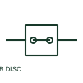
A disconnect terminal includes a documented separable path for circuit isolation or testing at the wiring level.
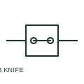
A knife-disconnect terminal opens its circuit path using a documented pivoting knife element.
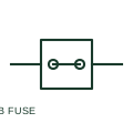
A fuse terminal integrates a fuse-link into a terminal connection path.
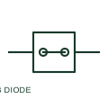
A diode terminal includes a semiconductor diode in a documented terminal path.
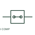
A component terminal incorporates a documented electrical component or component plug in its wiring path.
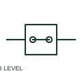
A multilevel terminal carries two or more documented connection levels within one terminal body.
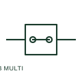
A multi-conductor terminal provides several connection points for its documented electrical path.
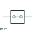
A PE terminal provides a documented protective-conductor connection, often including a specified connection to the mounting rail.
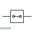
A sensor terminal organises supply, return and signal connections for a documented sensor wiring arrangement.
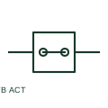
An actuator terminal organises supply, output and any protective-conductor connections for a documented actuator circuit.
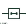
A plug-in terminal allows a documented terminal circuit to be disconnected through a removable mating part.
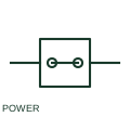
A high-current terminal provides a documented connection for large conductors and power circuits.
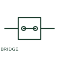
A terminal bridge intentionally connects specified terminal points to a common potential.
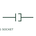
A plug/socket pair represents a detachable electrical connection with two mating sides.
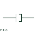
A plug-half representation identifies one side of a detachable connector.
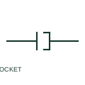
A socket-half representation identifies the mating interface for a detachable plug.
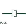
A wire splice intentionally joins documented conductors without a detachable connector interface.

An earth connection identifies a documented circuit connection to earth.
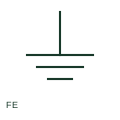
Functional earth serves an operational purpose such as a documented EMC or signal-reference connection.
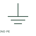
Protective equipotential bonding connects documented conductive parts as part of the protective arrangement.
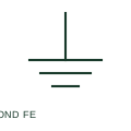
Functional equipotential bonding connects documented points for an operational or signal-related purpose.
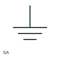
A surge arrester diverts a documented surge-related current through its protective path.
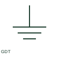
A gas-discharge tube provides a documented surge-protection path through gas breakdown.
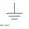
A spark-gap element provides a documented breakdown path across separated electrodes.
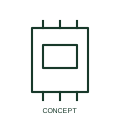
A marshalling interface organises field circuits and controller connections.
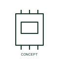
A feed-through terminal provides a defined wiring connection across a terminal position.
A protective-earth terminal provides the specified connection between conductors and the earthing arrangement.
A multi-level terminal groups distinct connections at several levels within one rail position.
A fuse terminal combines a terminal position with a selected fuse arrangement.
A disconnect terminal provides a defined separable point in a wiring circuit.
A CT test terminal supports the specified measuring and test connection arrangement.
A distribution block divides a supplied circuit among specified outgoing connections.
A pluggable terminal arrangement separates a wiring connector from its mating interface.
An end stop retains a specified terminal assembly on its mounting rail.
A marker strip carries identification for the terminal arrangement.
A cable gland secures and, where specified, seals a cable at an enclosure entry.
A cable-entry frame organises one or more cables through a documented enclosure opening.
A bulkhead connector provides a separable electrical or communication interface at a panel surface.
An earth bar provides a designated earthing connection point for multiple conductors.
A neutral bar groups specified neutral connections within an assembly.
AutomationDirect ZIPLinks is a terminal marshalling interface product family referenced for electrical equipment layout.
AutomationDirect DINnectors is a feed-through terminal block product family referenced for electrical equipment layout.
AutomationDirect Konnect-It DIN-rail terminals is a feed-through terminal block product family referenced for electrical equipment layout.
AutomationDirect Bimed cable glands is a cable gland product family referenced for electrical equipment layout.
AutomationDirect ZIPport Multi-Wire Connectors is a bulkhead connector product family referenced for electrical equipment layout.
AutomationDirect ZIPport Panel Interface Connectors is a bulkhead connector product family referenced for electrical equipment layout.
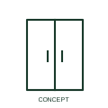
AutomationDirect Edison Power Distribution Blocks is a distribution terminal block product family referenced for electrical equipment layout.
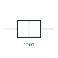
An assembly joining power-cable sections while maintaining the required conductor, insulation, screen and environmental interfaces.
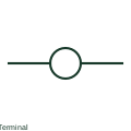
IEEE-oriented graphical reference for terminal connection, with public vendor evidence and drawing-reading notes.
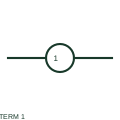
IEEE-oriented numbered connection-point form, with public vendor evidence and terminal-reading notes.
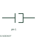
IEEE-oriented graphical reference for plug and socket connector pair, with public vendor evidence and drawing-reading notes.
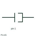
IEEE-oriented graphical reference for connector plug half, with public vendor evidence and drawing-reading notes.
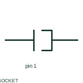
IEEE-oriented graphical reference for connector socket half, with public vendor evidence and drawing-reading notes.
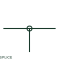
IEEE-oriented graphical reference for wire splice, with public vendor evidence and drawing-reading notes.
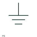
IEEE-oriented graphical reference for protective earth, with public vendor evidence and drawing-reading notes.
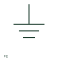
IEEE-oriented graphical reference for functional earth, with public vendor evidence and drawing-reading notes.
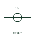
A cable marker identifies a cable association within a schematic conductor group.
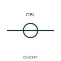
An additional-core marker associates another conductor with an existing cable record.

A twisted-pair indication identifies the documented association of two conductors as a twisted pair.
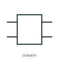
A generic device boundary groups the terminals belonging to one documented component or function.
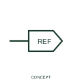
A source cross-reference identifies the originating side of a diagram continuation relationship.
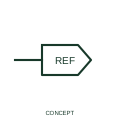
A destination cross-reference identifies the receiving side of a diagram continuation relationship.
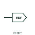
A reference-only arrow directs the reader to an associated wire continuation or annotation.
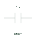
A one-line connector representation identifies a connector interface in a simplified circuit view.
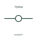
A one-line terminal identifies a termination point in a simplified circuit view.
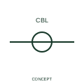
A one-line cable marker identifies the cable represented by a simplified connection line.
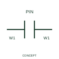
This form identifies a separable connector whose publisher representation preserves wire-number identity across the interface.
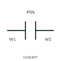
This form identifies a connector representation that allows wire-number identities to change across the interface.
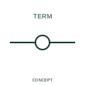
This terminal representation carries the associated wire identifier at the connection point.
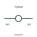
This representation identifies a terminal across which the publisher permits a wire-number change.
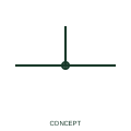
A junction indication marks a documented electrical connection between conductor branches.
An unconnected crossing shows conductors passing across each other in the drawing without an electrical junction.