GEN
Generator
An electrical generating source represented in a power-system drawing.
SLD / Schematic
Generation, storage, conversion and supporting equipment for microgrid power stations. Explore 94 references, with original explanations and public primary sources.
An electrical generating source represented in a power-system drawing.
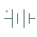
An electrochemical electrical source or storage element represented in a circuit.
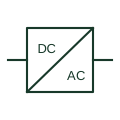
An identified interface converting electrical power between documented circuit forms.

A generic storage-equipment envelope linked to the selected battery system.

A generic envelope for the selected power-conversion equipment and its interfaces.

A generic generating-package envelope linked to official equipment and installation drawings.

An equipment assembly connecting a load to the selected supply source.
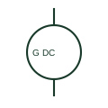
A DC generator converts mechanical input into a documented DC electrical output.
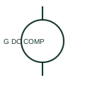
A compound-excited DC generator uses documented series and shunt excitation components.
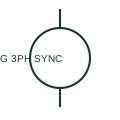
A three-phase synchronous generator supplies a documented AC source associated with its mechanical prime mover and excitation system.
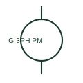
A permanent-magnet synchronous generator provides an AC source using a permanent magnetic excitation system.
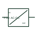
An AC/DC power supply converts a documented AC input to a DC output for control or auxiliary circuits.
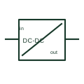
A DC/DC converter changes a documented DC input into another DC output.
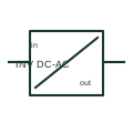
A DC/AC inverter converts a documented DC supply into an AC output.
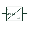
A DC UPS maintains a documented DC load supply during a specified input interruption using an associated energy store.
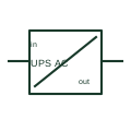
An AC UPS provides a documented AC load supply through its normal and backup operating arrangements.
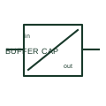
A capacitor buffer module stores energy for a documented short supply-interruption duty.
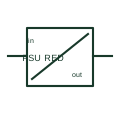
A redundancy module decouples documented power-supply inputs before they feed a common load circuit.
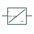
A photovoltaic inverter converts a documented PV DC input into an AC output and provides the selected PV control functions.
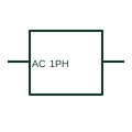
A single-phase AC source identifies a documented source boundary in a schematic or SLD.
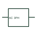
A three-phase AC source identifies a documented three-phase supply boundary.
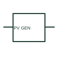
A photovoltaic generator represents the electrical production of PV cells or modules.
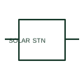
A solar generating station is a system-level representation of a documented solar-generation facility.
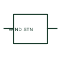
A wind generating station is a system-level representation of a documented wind-generation facility.
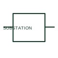
A substation representation identifies a documented facility boundary in a network or system diagram.
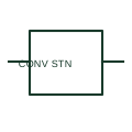
A converter-substation representation identifies a documented facility where an electrical conversion function forms part of the network connection.
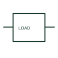
A generic electrical load identifies a documented consuming circuit or aggregate load on an SLD.
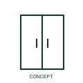
An AC UPS provides the specified continuity of supply to supported AC loads.
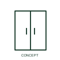
A maintenance bypass arrangement provides the documented alternate supply path around a UPS.
A day tank provides the selected local fuel supply arrangement for a generator.
A bulk tank stores fuel for the documented generator fuel system.
A transfer pump moves fuel along the documented tank supply arrangement.
An exhaust silencer is part of the specified engine exhaust path.
A flexible exhaust connection accommodates the specified engine/exhaust interface.
An exhaust stack routes the specified engine exhaust to a documented discharge location.
A radiator discharge duct directs the specified cooling airflow away from the generator.
A remote radiator forms part of the selected generator cooling circuit.
An acoustic canopy surrounds the selected generator with its documented access and ventilation arrangement.
A coolant heater supplies the selected standby engine heating function.
A starting battery supplies the documented engine starting circuit.
A paralleling controller coordinates specified generator and switching functions.
A PV combiner groups specified photovoltaic string connections and associated devices.
A PV inverter converts the selected array DC power to its specified AC interface.
A PV isolator arrangement provides the specified array-side DC switching interface.
An MPPT controller interfaces the selected photovoltaic source with a DC charging arrangement.
An inverter-charger interfaces a battery circuit with the specified AC supply/load system.
A BMS module performs the selected battery monitoring and control interface functions.
A battery disconnect assembly provides the documented DC isolation or switching arrangement.
A precharge arrangement controls the specified initial charging of a downstream DC interface.
A DC distribution module organises battery-side supply and outgoing circuits.
An energy-management controller coordinates the selected monitoring and dispatch interfaces.
An energy-storage container houses the selected storage, conversion and support equipment arrangement.
A battery cooling unit provides the selected thermal-control interface for a storage system.
A fire-system interface panel provides the documented connection between storage equipment and the project's fire system.
Schneider Electric TransferPacT is a source-transfer switch assembly product family referenced for electrical equipment layout.
A source-transfer assembly provides the documented switching arrangement between alternative supplies.
A lithium battery module stores energy and connects through the specified battery management arrangement.
Victron Energy MultiPlus-II is a battery inverter-charger product family referenced for electrical equipment layout.
Victron Energy Quattro is a battery inverter-charger product family referenced for electrical equipment layout.
Victron Energy SmartSolar MPPT RS is a mppt solar charge controller product family referenced for electrical equipment layout.
Victron Energy Cerbo GX is a energy-management controller product family referenced for electrical equipment layout.
Victron Energy Lynx Distributor is a battery dc bus distribution module product family referenced for electrical equipment layout.
Victron Energy Lynx Smart BMS NG is a battery management system module product family referenced for electrical equipment layout.
Victron Energy Lithium NG Batteries is a lithium battery module product family referenced for electrical equipment layout.
Victron Energy Multi RS Solar is a battery inverter-charger product family referenced for electrical equipment layout.
Victron Energy MultiPlus-II 2x 120V is a battery inverter-charger product family referenced for electrical equipment layout.
DEIF iE 250 controllers is a generator paralleling controller product family referenced for electrical equipment layout.
Dagartech BGPSW 15 ST is a diesel generator-set configuration documented on its official product page.
Dagartech DGB 415 ST is a diesel generator-set configuration documented on its official product page.
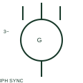
IEEE-oriented graphical reference for three-phase synchronous generator, with public vendor evidence and drawing-reading notes.
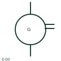
IEEE-oriented graphical reference for dc generator, with public vendor evidence and drawing-reading notes.
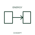
An outbound-energy qualifier identifies energy leaving the represented device or boundary.
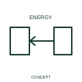
An inbound-energy qualifier identifies energy entering a represented device or system.
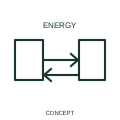
This qualifier identifies an energy interface intended to operate in both directions.
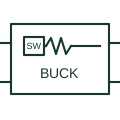
A switching converter arrangement used to produce a lower DC output from its input under the documented operating conditions.
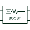
A switching converter arrangement used to obtain a higher DC output from its documented input range.
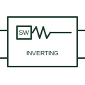
A buck-boost arrangement whose output polarity is opposite to its defined input reference.
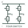
A non-inverting conversion arrangement with switching legs that support documented buck and boost operation.
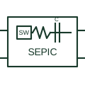
A non-inverting conversion topology using its documented inductive and series-capacitor energy-transfer arrangement.
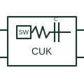
An inverting conversion topology using a capacitor as part of the energy-transfer path between inductive stages.
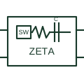
A non-inverting converter arrangement using its documented inductive and capacitive transfer circuit.
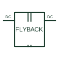
A conversion arrangement that uses coupled magnetic energy storage and transfers energy through the documented switching sequence.
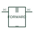
A conversion topology transferring power through coupled windings during the documented primary conduction interval.
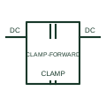
A forward converter arrangement with an actively controlled clamp/reset circuit.
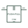
A converter arrangement driving two primary paths alternately through the documented coupled winding.
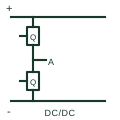
A DC conversion stage using one switching leg and the documented magnetic/secondary circuit.
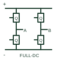
A DC conversion stage using two switching legs to apply the documented waveform to a magnetic primary.
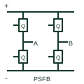
A full-bridge conversion arrangement controlled through the documented relative switching-leg phase shift.
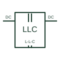
A converter arrangement using the documented resonant inductive/capacitive network and magnetic transfer path.
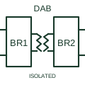
A conversion stage with controlled bridges on both sides of a coupled magnetic link.
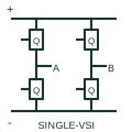
A switching bridge that forms a documented single-phase AC output from a DC-link source.
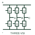
A three-leg bridge producing the documented three-phase output from a DC-link source.
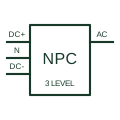
A multilevel switching arrangement using the documented split DC link and neutral-point clamping paths.
An actively switched AC/DC stage using a documented current-control and DC-link regulation arrangement.