AND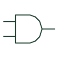
AND gate
A logic element whose output is true when all stated positive-logic inputs are true.
Schematic
Symbols, protection codes and equipment references for switchgear, switchboards, switchrooms and microgrids.
A logic element whose output is true when all stated positive-logic inputs are true.
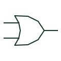
A positive-logic element whose output is true when at least one input is true.
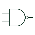
A logic gate that inverts the result of an AND operation.
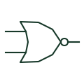
A logic gate that inverts an inclusive-OR result.
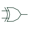
For two positive-logic inputs, produces a true output when the input states differ.
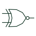
For two positive-logic inputs, produces a true output when the input states are equal.
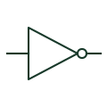
Produces the opposite logical state of its defined digital input.
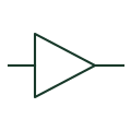
Transfers a digital state through a non-inverting logic output stage.
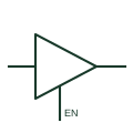
A digital output stage that can drive logical states or enter its documented high-impedance state.
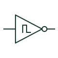
A digital inverter with hysteresis between its input switching thresholds.
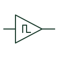
A non-inverting digital element with separate rising and falling input thresholds.
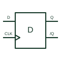
Captures its data input at the documented positive clock edge and retains that digital state.
Understand symbols, equipment tags and function numbers—and know when a generic object needs a manufacturer drawing.