CT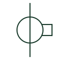
Current transformer
A current-measurement transformer used with metering and protection equipment.
SLD / Schematic
Instrument transformers, measurement, protection relays and device-function numbers. Explore 237 references, with original explanations and public primary sources.
A current-measurement transformer used with metering and protection equipment.
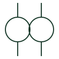
A transformer providing a voltage signal for metering or protection.

Checks documented synchronising conditions before a permitted connection.
A function responding to voltage below its configured operating criteria.

A function responding to power with a specified direction and operating condition.
A current phase-balance or reverse-phase function used in documented protection applications.
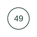
A thermal protection function for a documented machine or transformer application.

An overcurrent function without an intentional operating time delay in its instantaneous application.

An overcurrent function with a documented time characteristic.

A function responding to voltage above its configured operating criteria.

An overcurrent function with a documented direction criterion.
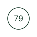
A function coordinating a documented automatic reclosing sequence.

A function responding to a documented frequency condition.

A lockout function or device with the documented reset and blocking behaviour.

A function comparing documented electrical quantities across a protection zone.
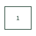
Starts or enables the principal operating sequence of a machine or power-system unit.
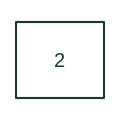
Introduces a deliberate interval before a starting or closing operation is permitted.
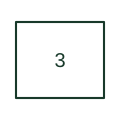
Checks a required equipment state before the operating sequence proceeds.
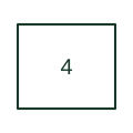
Switches the main control or operating circuit under the unit's master command.
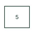
Initiates a machine or unit shutdown by removing the relevant operating permission.
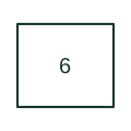
Connects a machine to the electrical supply used during starting.
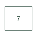
Responds to how quickly a monitored quantity changes rather than only its absolute magnitude.
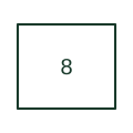
Isolates the supply feeding a control circuit or control-power bus.
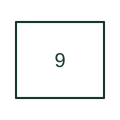
Changes the operating connection to reverse the direction of a machine or power circuit.
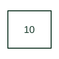
Selects or determines the order in which multiple units enter an operating sequence.
Identifies a device that performs several separately described protection or control functions.
Responds when machine speed exceeds the documented operating criterion.
Recognises a speed condition associated with synchronism during a machine sequence.
Responds to machine speed below the required operating level.
Adjusts or supervises the difference between two speed or frequency references.
Identifies equipment carrying data between control, protection or monitoring devices.
Changes a circuit connection to bypass a component or provide a discharge path.
Controls a machine action that changes its operating speed during a sequence.
Changes the machine connection from its starting arrangement to its running arrangement.
Commands a valve through an electrical actuator or solenoid.
Uses measured voltage and current to assess an electrical distance or impedance characteristic.
Switches an equalising connection used in a machine or generator arrangement.
Controls heating, cooling or another process action using a temperature input.
Supervises the voltage-to-frequency relationship associated with magnetic overexcitation.
Responds to the temperature of equipment or a monitored part of that equipment.
Provides electrical indication that combustion flame is present or absent.
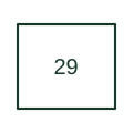
Provides a contactor-operated disconnection within a machine or power circuit.
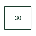
Operates an indication system that presents a detected condition to the operator.
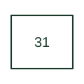
Connects or controls a separately supplied excitation arrangement for a machine.
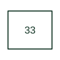
Changes an electrical indication when a mechanism reaches a defined physical position.
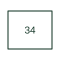
Coordinates the steps of a machine or switching sequence.
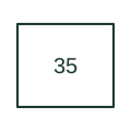
Changes the brush or slip-ring arrangement as part of a wound-rotor machine sequence.
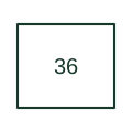
Supervises or establishes a required electrical polarity condition.
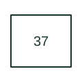
Recognises a current or power level below the documented minimum operating criterion.
Supervises an abnormal condition at a machine bearing, often using temperature or mechanical sensing.
Converts a monitored mechanical condition into an electrical alarm or protection signal.
Detects an abnormal machine excitation condition using the implementation's field or electrical measurements.
Applies or removes the electrical connection to a machine field circuit.
Connects a machine to the supply or connection used for normal running.
Selects an operating circuit, control source or mode through a manual action.
Starts the next unit or operating step when the documented sequence condition is met.
Reports an ambient atmospheric condition relevant to equipment operation.
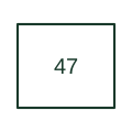
Supervises phase order or voltage imbalance using the selected device's voltage inputs.
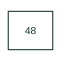
Detects that an operating or starting sequence has not completed as required.
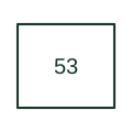
Supervises an exciter or DC generator condition in a machine control arrangement.
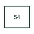
Controls engagement of the turning gear used to rotate a large machine at low speed.
Supervises power factor according to the selected relay's electrical measurement method.
Initiates application of excitation at the appropriate step of a machine starting sequence.
Makes a defined short-circuit or earth connection for the purpose shown in the machine or apparatus scheme.
Detects failure or abnormal operation in a rectifier arrangement.
Compares related measured circuits or quantities to detect an abnormal imbalance.
Monitors the density of a medium used by electrical equipment.
Introduces a documented delay in a stopping or opening operation.
Provides an electrical response to a gas, liquid or other pressure condition.
Identifies an earth or ground fault using the circuit arrangement specified for the device.
Regulates the operating speed or mechanical input of a generating or rotating unit.
Controls limited machine movements or, in modern motor relays, supervises the allowed starting duty.
Restrains or coordinates another protection action under the specified system condition.
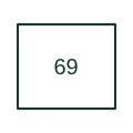
Permits or prevents an equipment operation according to a selected control condition.
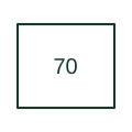
Provides adjustable resistance in a control, excitation or machine circuit.
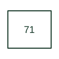
Signals a defined level condition in the monitored equipment.
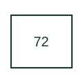
Interrupts or switches a direct-current power circuit using a breaker selected for DC duty.
Switches a resistor used to impose, remove or change electrical load in a machine arrangement.
Provides an electrical alarm output for a documented monitored condition.
Moves an apparatus between defined physical positions.
Supervises excessive current in a direct-current circuit.
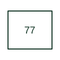
Transmits a measured quantity from its local measurement point to a remote indication or monitoring system.
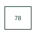
Supervises the angular relationship or loss of synchronism of an electrical system or machine.
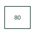
Reports a flow condition in a monitored gas or liquid circuit.
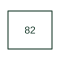
Supervises a DC load condition as part of a documented reclosing arrangement.
Automatically selects between control circuits or operating sources under defined conditions.
Provides the motive action that operates electrical apparatus.
Receives a communication-assisted protection signal used in a pilot or carrier scheme.
Identifies a motor or motor-generator serving an auxiliary equipment function.
Adjusts equipment to maintain the controlled electrical or operating quantity.
Uses a voltage relationship with a defined direction criterion in a specialist protection or control scheme.
Combines voltage and power directional criteria in the specified control or protection arrangement.
Changes the machine excitation connection or arrangement as part of a controlled field sequence.
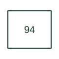
Initiates a tripping action or provides the trip-related logic described in the scheme.
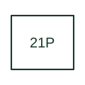
Evaluates an impedance characteristic for phase-fault loops on the protected circuit.
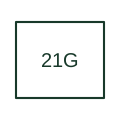
Evaluates a distance characteristic for a phase-to-earth fault loop.
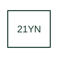
Uses earth-fault voltage and current relationships to assess an admittance-based directional criterion.
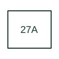
Supervises low voltage using the auxiliary voltage input identified by the selected relay.
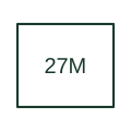
Supervises low voltage using the relay's main voltage measurement inputs.
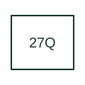
Combines a reactive-power criterion with undervoltage supervision in the cited interconnection application.
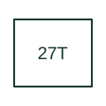
Supervises a voltage-time ride-through criterion used in a generator or interconnection application.
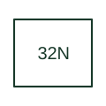
Uses residual voltage and current to assess earth-fault power in the documented neutral-system application.
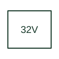
Supervises forward or reverse reactive power using the selected relay's power-direction convention.
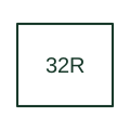
Detects active power flowing opposite to the defined generator or circuit direction.
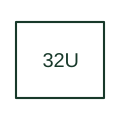
Supervises active power below the documented operating criterion.
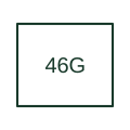
Supervises generator current imbalance using the manufacturer's machine protection implementation.
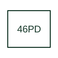
Uses current-sequence relationships to detect a phase-discontinuity condition.
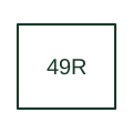
Uses resistance-temperature-detector measurements for an equipment thermal protection function.
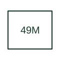
Estimates motor thermal duty using the selected relay's motor thermal model.

Supervises phase-current magnitude for the instantaneous overcurrent element.
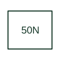
Supervises the neutral or residual-current quantity identified by the protection scheme.
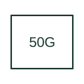
Supervises the ground-current input or ground-fault quantity identified by the selected relay.
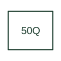
Supervises negative-sequence current for an instantaneous overcurrent element.
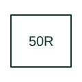
Supervises an instantaneous residual-current element calculated from phase-current measurements in the cited Eaton family.
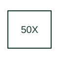
Supervises the instantaneous element using a separately measured ground or neutral input in the cited Eaton family.
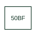
Initiates the documented backup action when a breaker does not clear the monitored condition after a trip initiation.
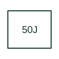
Supervises a motor current condition associated with a jam or stall in the cited relay application.
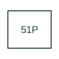
Supervises phase overcurrent using the selected time-current characteristic or intentional operating delay.
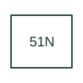
Supervises neutral or residual overcurrent with the configured timing characteristic.
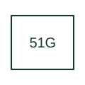
Supervises ground-current overcurrent with the timing defined by the selected relay and scheme.
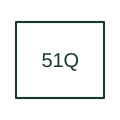
Supervises negative-sequence current using a time-dependent operating criterion.
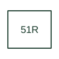
Applies time-overcurrent protection to the calculated residual-current input in the cited Eaton family.
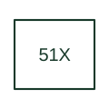
Applies time-overcurrent protection to a separately measured ground or neutral input in the cited Eaton family.
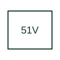
Changes overcurrent operation according to the measured voltage using the relay's documented voltage-dependent method.
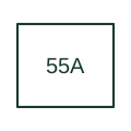
Supervises the apparent power-factor quantity defined in the cited relay family.
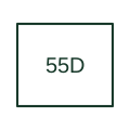
Supervises displacement power factor as defined by the relay's fundamental-frequency measurements.
Supervises a residual or neutral voltage used by the selected earth-fault or neutral-displacement scheme.
Supervises the negative-sequence component derived from three-phase voltage measurements.
Supervises high voltage on the auxiliary measurement input in the cited Eaton family.
Supervises high voltage using the main three-phase inputs in the cited Eaton family.
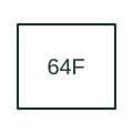
Detects an earth fault in a machine field circuit using the selected field-ground detection arrangement.
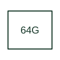
Supervises generator stator earth faults using the selected stator-ground protection method.
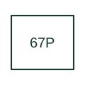
Combines phase-current overcurrent operation with the scheme's direction criterion.
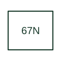
Supervises neutral or residual overcurrent with a documented directional criterion.
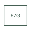
Supervises a ground-current quantity with direction determined by the selected relay's polarising method.
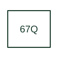
Uses negative-sequence quantities to supervise overcurrent operation in a defined direction.
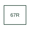
Applies directional overcurrent to calculated residual current in the cited Eaton application.
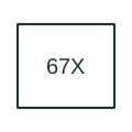
Applies directional supervision to the separately measured ground or neutral current element in the cited Eaton family.
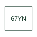
Assesses earth-fault behaviour using the manufacturer's multifrequency admittance-based method.
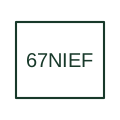
Supervises transient or intermittent earth-fault behaviour in the documented feeder application.
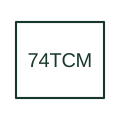
Monitors the electrical integrity of a documented breaker trip-coil circuit.
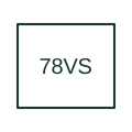
Supervises an abrupt change in the measured voltage phase angle using the selected relay's vector-shift method.
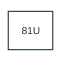
Supervises frequency below the defined operating criterion.
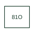
Supervises frequency above the defined operating criterion.
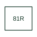
Supervises the rate at which measured electrical frequency changes.
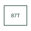
Compares currents associated with a transformer protection zone using the selected relay's differential method.
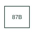
Compares currents at the boundaries of a busbar protection zone.
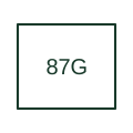
Compares current measurements bounding the selected generator differential zone.
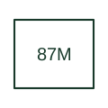
Compares current measurements defining a motor differential protection zone.
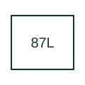
Compares current information from the terminals of a protected line using a communication-assisted differential scheme.
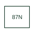
Identifies a differential scheme involving neutral or residual-current quantities as defined by the equipment documentation.
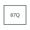
Compares negative-sequence current information across a differential protection zone.
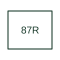
Uses a differential operating quantity with restraint in the cited transformer-relay application.
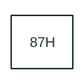
Provides the documented high-set or unrestrained differential element in the cited relay family.
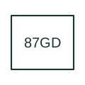
Compares ground-fault-related currents for the restricted zone defined by the cited relay application.
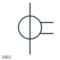
A CT with two secondary windings supplies two documented secondary circuits.
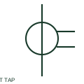
A tapped CT secondary provides alternative documented transformation ratios through different terminal combinations.
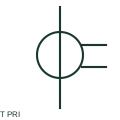
This CT representation explicitly identifies the primary conductor passing through the measurement location.
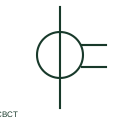
A core-balance CT measures residual current from the net magnetic effect of conductors passing through its window.
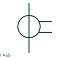
A residual CT connection combines secondary currents from phase CTs to obtain a residual-current input.
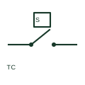
A thermocouple produces a temperature-dependent voltage associated with its dissimilar-metal junction system.
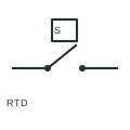
An RTD is a temperature sensor whose resistance changes with temperature.
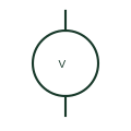
A voltmeter indicates electrical potential difference between its measurement inputs.
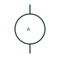
An ammeter indicates current from a direct or instrument-transformed measurement circuit.
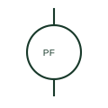
A power-factor meter indicates the relationship between real and apparent power according to the instrument's measurement method.
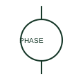
A phase-angle meter indicates the phase relationship between documented signals.
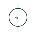
A frequency meter indicates the frequency of its measured input.
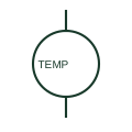
A temperature indicator displays the temperature derived from its specified sensor or input.
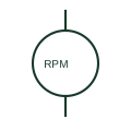
A tachometer indicates rotational speed from its documented sensor or electrical input.

A running-hours meter accumulates elapsed time while its specified enabling condition is active.
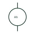
An ampere-hour meter integrates current over time for a documented measurement purpose.
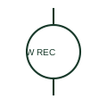
A recording wattmeter measures active power and records it according to the specified instrument.
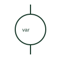
A reactive-power meter indicates reactive power using the instrument's documented voltage and current inputs.
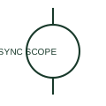
A synchronoscope indicates the phase relationship and relative frequency behaviour of two AC sources.
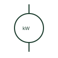
An active-power indicator displays real power derived from its specified measurement inputs.
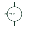
A differential voltmeter indicates a difference between documented voltage inputs.
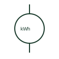
An active-energy meter accumulates active power over time.
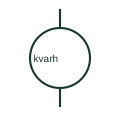
A reactive-energy meter accumulates reactive power over time according to the specified register convention.
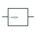
A maximum-current relay changes its output when the measured current meets a configured high-current condition.
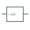
A minimum-current relay operates according to a configured low-current condition.
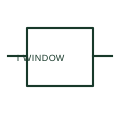
A current-window relay supervises both minimum and maximum current conditions.
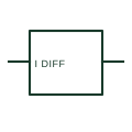
A differential-current relay responds to the relationship between specified current inputs.
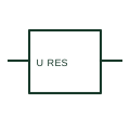
A residual-voltage relay responds to the specified residual-voltage measurement.
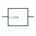
A loss-of-voltage relay changes its output for a documented absence-of-voltage condition.
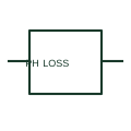
A phase-loss relay supervises the presence of the specified phases in a three-phase system.
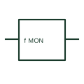
A frequency relay issues a documented output for a configured frequency condition.
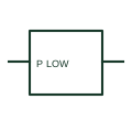
A minimum active-power relay operates according to a configured low active-power condition.
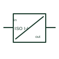
A current signal isolator transfers a documented analog current input to an output while providing the specified electrical separation.
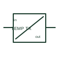
A temperature transducer converts a documented temperature-sensor input into an instrument signal.
A relay panel houses protection, control, test and terminal equipment for defined circuits.
A panel power meter measures the specified electrical quantities through its input interfaces.
An energy submeter measures consumption for a specified circuit or group of loads.
A window CT surrounds a conductor or busbar to provide the specified current measurement.
A split-core CT can be assembled around the specified existing conductor.
A voltage-transformer assembly provides the specified voltage measurement interface.
A current shunt provides a specified DC current-measurement interface.
Schneider Electric MiCOM protection relays is a protection relay ied product family referenced for electrical equipment layout.
Schneider Electric PowerLogic PM5000 is a panel power meter product family referenced for electrical equipment layout.
Schneider Electric PowerLogic PM8000 is a panel power meter product family referenced for electrical equipment layout.
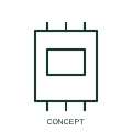
Schneider Electric PowerLogic P5 protection relays is a protection relay ied product family referenced for electrical equipment layout.
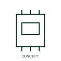
A protection relay IED implements the selected measurement, protection and control functions.
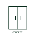
Victron Energy SmartShunt is a battery current shunt product family referenced for electrical equipment layout.
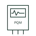
A measuring device used to monitor electrical quantities and documented power-quality events or waveform characteristics.
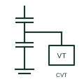
An instrument transformer using a capacitive voltage divider and an electromagnetic unit to supply documented voltage measurement or protection signals.
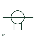
IEEE-oriented graphical reference for current transformer, with public vendor evidence and drawing-reading notes.
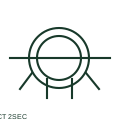
IEEE-oriented graphical reference for current transformer with two secondaries, with public vendor evidence and drawing-reading notes.
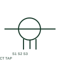
IEEE-oriented graphical reference for tapped-secondary current transformer, with public vendor evidence and drawing-reading notes.
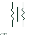
IEEE-oriented graphical reference for voltage transformer, with public vendor evidence and drawing-reading notes.
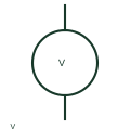
IEEE-oriented graphical reference for voltmeter, with public vendor evidence and drawing-reading notes.
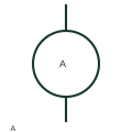
IEEE-oriented graphical reference for ammeter, with public vendor evidence and drawing-reading notes.
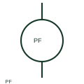
IEEE-oriented graphical reference for power-factor meter, with public vendor evidence and drawing-reading notes.
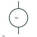
IEEE-oriented graphical reference for frequency meter, with public vendor evidence and drawing-reading notes.
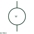
IEEE-oriented graphical reference for recording wattmeter, with public vendor evidence and drawing-reading notes.
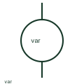
IEEE-oriented graphical reference for reactive-power meter, with public vendor evidence and drawing-reading notes.
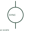
IEEE-oriented graphical reference for synchronoscope, with public vendor evidence and drawing-reading notes.
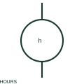
IEEE-oriented graphical reference for running-hours meter, with public vendor evidence and drawing-reading notes.
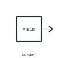
This qualifier identifies response to a magnetic field in the represented function.
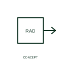
An ionising-radiation qualifier identifies the radiation role attached to a measuring or operating function.
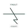
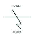
This indication marks the presumed location of a fault or failure in a diagnostic diagram.
An insulation-failure indication identifies the documented insulation-related failure condition.
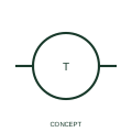
This representation distinguishes a thermocouple circuit expanded to show its terminal-board interface.
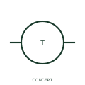
A pyrometer indication identifies the documented temperature-measurement display function.
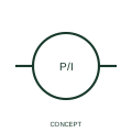
This representation identifies conversion of a pressure input to a current-signal output.
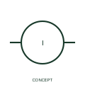
This representation identifies the publisher's single-phase AC/DC current-conversion function.
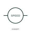
A tachometric dynamo indication identifies a speed-related generating measurement function.
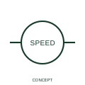
This representation distinguishes an impulse-output speed-measurement function.
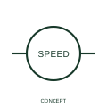
This representation identifies optical speed-sensing in the publisher's tachometric family.
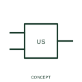
An ultrasonic-switch representation identifies presence or distance switching using an ultrasonic sensing principle.
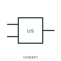
This form identifies a normally-open switching output in the ultrasonic sensor family.
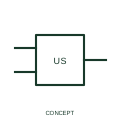
This form identifies a normally-closed switching output in the ultrasonic sensor family.
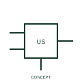
This representation distinguishes a three-wire ultrasonic sensor interface from a simple contact depiction.
This representation identifies selection among phase-to-phase voltage measurement connections.
This representation identifies selection among phase-to-neutral voltage measurement connections.
This representation identifies a selector covering phase-to-phase and phase-to-neutral voltage measurements.
This representation distinguishes voltage selection between two three-phase networks.
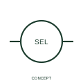
This representation identifies selection among three current-measurement points.
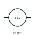
This representation identifies selection among four current-measurement points.