NO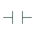
Normally open contact
A contact shown open in the normal state defined for its device.
Schematic
Contacts, coils, control devices, timing, interlocking and automation references. Explore 296 references, with original explanations and public primary sources.
A contact shown open in the normal state defined for its device.
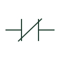
A contact shown closed in the normal state defined for its device.
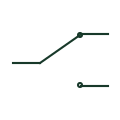
A contact arrangement switching a common connection between two contact paths.

The operating element associated with a relay and its separately drawn contacts.

An electrically operated switching device commonly used for repeated switching duties.
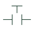
A pushbutton contact normally shown open before actuation.
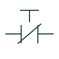
A pushbutton contact normally shown closed before actuation.
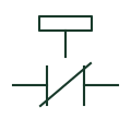
An identified emergency-stop operator and its documented contact arrangement.

An operator switch selecting between documented control positions.

A visual indicator associated with a documented control or equipment condition.
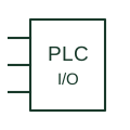
A controller interface point connecting field signals to an identified module channel.

A resistive component with its value and purpose documented separately.
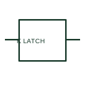
A mechanically latched relay retains a documented state after the initiating electrical command is removed.
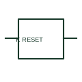
A reset coil releases or changes the retained state of its associated latching relay.
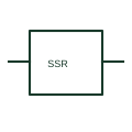
A solid-state relay switches an output through semiconductor circuitry in response to a control input.
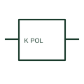
A polarised relay has operation or a specified response that depends on the documented electrical polarity.
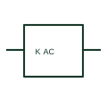
An AC relay coil is intended for a specified alternating-current control supply.
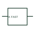
A high-speed relay has a documented operating response intended for duties where relay timing matters.
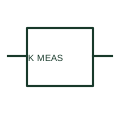
A measuring relay responds to a measured electrical quantity and issues an output according to its configuration.
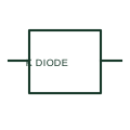
A relay with diode suppression includes a diode associated with its coil to limit the transient on de-energisation.
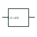
A relay assembly with diode and LED combines coil transient suppression and a visible energisation indicator.
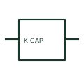
A relay with a capacitor suppression element includes a documented capacitive network associated with the coil.
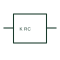
A relay RC suppression network uses resistance and capacitance associated with the coil circuit.
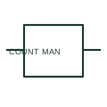
A manually reset counter relay records qualifying events and retains a count until the documented reset action.
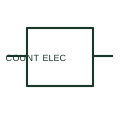
An electrically reset counter relay has a separate reset command or documented electronic reset mechanism.
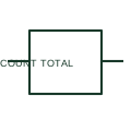
A non-resettable counter records events without a normal user reset function.
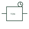
An on-delay timer postpones a specified output transition after its timing condition becomes active.
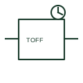
An off-delay timer holds a specified output condition for a documented period after its initiating condition is removed.
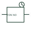
An on-delay NO contact changes from its unoperated open state only after the associated timing condition has persisted for the documented delay.
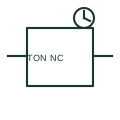
An on-delay NC contact opens after the associated timing condition has persisted for its documented interval.
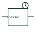
An off-delay NO contact retains the documented operated state for an interval after the timer trigger is removed.
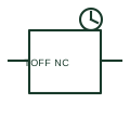
An off-delay NC contact returns to its documented normally-closed state after the delay following removal of the timing trigger.
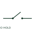
A maintained NO contact retains the actuated closed position according to its mechanism or control arrangement.
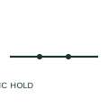
A maintained NC contact retains its actuated position until the documented return action occurs.

A manually unlatched NO contact includes a mechanical retaining action released by a documented manual operation.
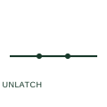
A manually unlatched NC contact has a mechanical retained state and a documented manual release.

An early-make NO contact closes earlier in the mechanism sequence than specified associated contacts.
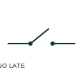
A late-make NO contact closes later in a documented mechanism sequence than associated contacts.
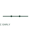
An early-break NC contact opens earlier in a documented mechanical sequence than associated contacts.
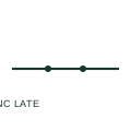
A late-break NC contact opens later in the documented operating sequence than specified associated contacts.
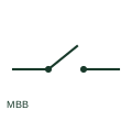
A make-before-break changeover contact establishes the next path before releasing the previous path during its documented transfer.
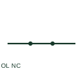
An overload trip NC contact opens on the documented overload relay operation.
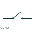
An overload alarm NO contact closes on the documented overload relay operation.
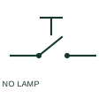
An illuminated NO pushbutton combines a manual normally-open contact function with an indication lamp.
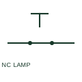
An illuminated NC pushbutton combines a normally-closed manual contact with a lamp in the operator assembly.

A maintained NO pushbutton stays in its actuated condition until the documented return operation.
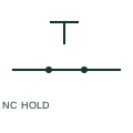
A maintained NC pushbutton retains its actuated open state until the documented return action.
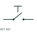
A key-operated NO switch closes a contact through an authorised key mechanism.
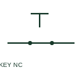
A key-operated NC switch opens its reference closed contact through the key mechanism.

A latched key-operated switch retains its commanded position according to the selected mechanism.
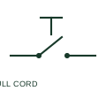
A pull-cord switch converts a cord-operated mechanical action into an electrical contact change.
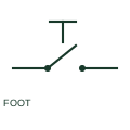
A foot-operated switch uses a pedal mechanism to change an electrical contact.
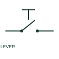
A lever-operated switch changes contact state through a manually operated lever.
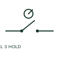
A three-position maintained selector stays at the selected position until manually moved.
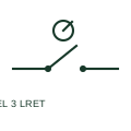
This three-position selector has a documented spring return from its left position.
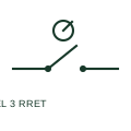
This three-position selector returns from its right position according to its mechanism.
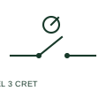
A centre-return selector returns from both outer positions to its documented central rest position.
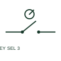
A three-position key selector combines position selection with a key-operated mechanism.
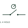
A four-position maintained selector provides four stable operating choices.
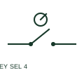
A four-position key selector provides key-controlled selection among four documented positions.
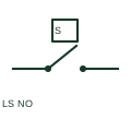
A normally-open limit switch closes when the documented mechanical travel or position condition actuates it.
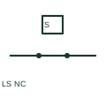
A normally-closed limit switch opens when the documented mechanical position actuates it.
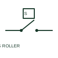
A roller-operated limit switch transfers equipment motion through a roller actuator to its electrical contacts.
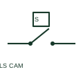
A cam-operated limit switch changes its electrical contact state when a defined cam profile reaches the actuator.
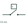
A pressure-operated NO switch closes when its documented pressure condition actuates the mechanism.
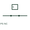
A pressure-operated NC switch opens under its documented actuation condition.
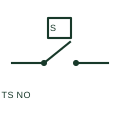
A temperature-operated NO switch changes from open to closed under its specified actuation condition.
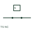
A temperature-operated NC switch opens under a documented thermal condition.
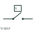
A self-operating thermal switch responds directly to its thermal condition rather than through a separate powered relay input.
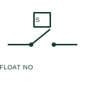
A float-operated NO level switch changes contact state through a float mechanism at a documented fluid level.
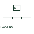
A float-operated NC level switch opens when its documented level condition actuates the mechanism.
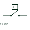
A liquid-flow switch issues a contact state when a documented flow condition actuates it.
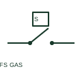
A gas-flow switch changes contact state for a specified gas-flow condition.
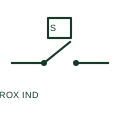
An inductive proximity switch detects a documented target without a mechanical contact actuator.
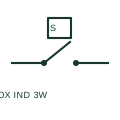
A three-wire inductive proximity switch uses separate supply, common and output conductors.
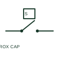
A capacitive proximity switch detects a target through a change in its sensing capacitance.
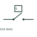
A magnetic proximity switch detects a documented magnetic target or field condition.
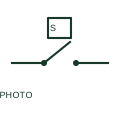
A photoelectric emitter-receiver device uses an optical path to determine a switching output.
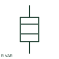
A variable resistor provides a documented adjustable resistance in a circuit path.

A potentiometer uses a movable contact on a resistive element to provide a documented adjustable divider or resistance.
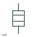
A light-dependent resistor changes resistance according to illumination.
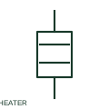
A heating element converts electrical energy to heat in a documented circuit.
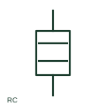
An RC network combines resistance and capacitance in a specified circuit arrangement.
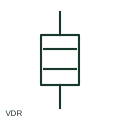
A varistor is a voltage-dependent resistive component used in a documented circuit, often for transient limiting.
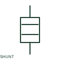
A current-measuring shunt produces a documented voltage drop corresponding to current through a resistive element.
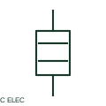
An electrolytic capacitor has a specified capacitance, voltage rating and any documented polarity requirement.
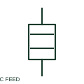
A feedthrough capacitor is arranged with a conductor path and a documented capacitive connection used in filtering.
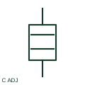
An adjustable capacitor provides a documented variable capacitance.
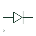
A diode provides a semiconductor path with documented directional conduction characteristics.
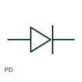
A photodiode is a light-sensitive semiconductor device used in a documented sensing circuit.
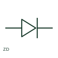
A Zener diode is a semiconductor component intended for a documented reverse-breakdown operating function.
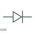
A DIAC is a bidirectional triggering semiconductor device used in a documented control circuit.
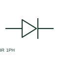
A single-phase bridge rectifier converts its specified AC input to a DC output through a bridge arrangement.
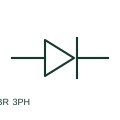
A three-phase bridge rectifier converts a documented three-phase AC input into a DC output.
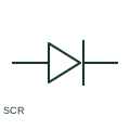
An SCR is a thyristor with a gate-controlled triggering function in its documented circuit.
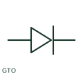
A gate-turn-off thyristor has a documented gate-controlled turn-off capability.
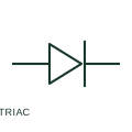
A TRIAC is a bidirectional thyristor used for a documented AC switching or control function.
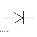
A bidirectional breakdown diode provides a documented voltage-limiting semiconductor path in both polarities.

A transformer-fed indicator lamp includes a documented internal voltage-conversion arrangement.

A push-to-test indicator lamp allows a documented local test of the lamp circuit.

An LED indicator assembly provides a documented visual signal using a semiconductor light source.

A flashing indicator lamp provides a documented intermittent visual indication.

A flashing beacon gives a documented conspicuous visual signal.

A rotating beacon provides a documented rotating visual signal through its specified mechanism or assembly.
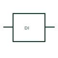
A PLC digital input reads a documented discrete electrical state from field wiring.
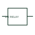
A PLC relay output switches a documented contact path through the module's relay interface.
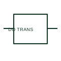
A PLC transistor output switches a documented electronic path for a field load.
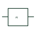
A PLC analog input measures a documented voltage, current or sensor quantity.
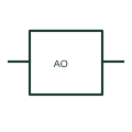
A PLC analog output provides a documented variable voltage or current signal to another device.
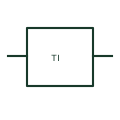
A PLC temperature input connects a documented RTD, thermocouple or compatible sensor through the selected module.

A power contactor switches a power circuit through an electrically operated mechanism.

A reversing assembly uses coordinated switching devices to change a motor connection sequence.

A star-delta starter arranges switching devices to change a motor winding connection during starting.

A thermal overload relay monitors motor-circuit loading and operates associated control contacts.

An electronic overload device provides the specified motor monitoring and trip functions.

A soft starter controls motor starting through power-electronic switching.

A variable-frequency drive supplies a controlled-frequency motor output.

A braking resistor dissipates energy when specified as part of a drive braking system.
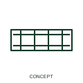
A DIN-rail power supply converts an input supply into a specified DC auxiliary supply.
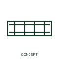
A DC/DC converter changes a DC supply to the specified output arrangement.

A redundancy module combines specified supply paths for an auxiliary DC system.

A buffer module supports a DC bus through specified short supply interruptions.

A DC UPS module manages continuity of a DC auxiliary supply with its specified energy-storage interface.

A battery charger maintains a specified battery supply or starting battery system.

A PLC CPU executes the programmed control logic of an automation system.

A PLC power module supplies the specified controller and expansion system.

A digital input module brings discrete field states into a controller.

A digital output module switches or signals discrete outputs under controller command.

An analogue input module receives the specified continuous measurement signals.

An analogue output module sends the specified continuous command signals.

A remote I/O station places input and output interfaces away from a controller CPU.

An HMI presents operating information and control interfaces to the user.

An industrial panel computer provides a computing platform within an equipment arrangement.

An industrial Ethernet switch interconnects devices in the specified communication network.

A remote-access router provides the specified network interface between control equipment and other networks.

A gateway connects the documented communication protocols or network boundaries.

An interface relay separates a controller signal from the specified switched circuit.

A relay socket supports a plug-in relay and its associated connections.

A timer relay changes its outputs according to the selected time function.

A safety relay performs specified monitored control functions within a documented safety circuit.

A signal conditioner converts or isolates the specified instrumentation signal.

An emergency stop station houses the specified emergency-control actuator and contacts.

A pilot-light station displays the documented equipment states through its lamps.

A selector station provides the selected maintained or returning control positions.

A trapped-key arrangement coordinates access or switching through the selected mechanical key sequence.

A local control station houses the specified operator actuators and contacts.

AutomationDirect BRX Series PLC is a plc cpu module product family referenced for electrical equipment layout.

AutomationDirect CLICK PLCs is a plc cpu module product family referenced for electrical equipment layout.

AutomationDirect Productivity1000 PAC is a plc cpu module product family referenced for electrical equipment layout.

AutomationDirect Productivity2000 PAC is a plc cpu module product family referenced for electrical equipment layout.

AutomationDirect Productivity3000 PAC is a plc cpu module product family referenced for electrical equipment layout.

AutomationDirect Terminator Field I/O is a remote i/o station product family referenced for electrical equipment layout.

AutomationDirect Protos X Field I/O is a remote i/o station product family referenced for electrical equipment layout.

AutomationDirect C-more Panels is a hmi touchscreen product family referenced for electrical equipment layout.

AutomationDirect C-more Micro Graphic Panels is a hmi touchscreen product family referenced for electrical equipment layout.

AutomationDirect GS and DURApulse AC drives is a variable-frequency drive product family referenced for electrical equipment layout.

AutomationDirect Stride VPN is a industrial vpn router product family referenced for electrical equipment layout.

AutomationDirect AcuAmp is a signal conditioner product family referenced for electrical equipment layout.

Fuji Electric SC contactors and thermal overload relays is a power contactor product family referenced for electrical equipment layout.

Fuji Electric SC-NEXT contactors is a power contactor product family referenced for electrical equipment layout.

Fuji Electric Orange Line / Odyssey contactors is a power contactor product family referenced for electrical equipment layout.

Fuji Electric Combination starters is a power contactor product family referenced for electrical equipment layout.

Fuji Electric SK contactors and relays is a power contactor product family referenced for electrical equipment layout.

TDK-Lambda D1SE120-xx-A3 is a din-rail ac/dc power supply product family referenced for electrical equipment layout.

TDK-Lambda D1SE240-xx-A3 is a din-rail ac/dc power supply product family referenced for electrical equipment layout.

TDK-Lambda D1SE480-xx-A3 is a din-rail ac/dc power supply product family referenced for electrical equipment layout.

TDK-Lambda DBM20 is a dc buffer module model referenced for electrical equipment layout.

TDK-Lambda DRB15 is a din-rail ac/dc power supply model referenced for electrical equipment layout.

TDK-Lambda DRB30 is a din-rail ac/dc power supply model referenced for electrical equipment layout.

TDK-Lambda DRB480 is a din-rail ac/dc power supply model referenced for electrical equipment layout.

TDK-Lambda DRF960 is a din-rail ac/dc power supply model referenced for electrical equipment layout.

TDK-Lambda DRM40 is a dc redundancy module model referenced for electrical equipment layout.

TDK-Lambda DUSH960-1248-1M is a dc ups module model referenced for electrical equipment layout.

PULS QS20.241 is a din-rail ac/dc power supply model referenced for electrical equipment layout.

Invertek Drives Optidrive Eco is a variable-frequency drive product family referenced for electrical equipment layout.

Schneider Electric TeSys K contactors is a power contactor product family referenced for electrical equipment layout.

Schneider Electric TeSys Giga contactors is a power contactor product family referenced for electrical equipment layout.

Schneider Electric TeSys Deca overload relays is a thermal overload relay product family referenced for electrical equipment layout.

Schneider Electric PowerLogic T500 Substation Controller is a substation rtu product family referenced for electrical equipment layout.

A substation RTU provides the specified monitoring, control and communications interface.

Victron Energy Skylla-IP65 is a battery charger product family referenced for electrical equipment layout.

Westermo PS2-60 is a din-rail ac/dc power supply model referenced for electrical equipment layout.

Westermo Lynx 5612-E-F4G-T8G-LV is a industrial ethernet switch model referenced for electrical equipment layout.
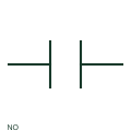
IEEE-oriented graphical reference for normally open contact, with public vendor evidence and drawing-reading notes.
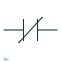
IEEE-oriented graphical reference for normally closed contact, with public vendor evidence and drawing-reading notes.
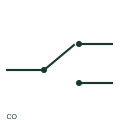
IEEE-oriented graphical reference for changeover contact, with public vendor evidence and drawing-reading notes.
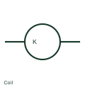
IEEE-oriented graphical reference for relay coil, with public vendor evidence and drawing-reading notes.
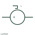
IEEE-oriented graphical reference for mechanically latched relay coil, with public vendor evidence and drawing-reading notes.
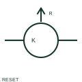
IEEE-oriented graphical reference for relay reset coil, with public vendor evidence and drawing-reading notes.
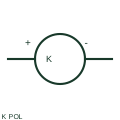
IEEE-oriented graphical reference for polarised relay coil, with public vendor evidence and drawing-reading notes.
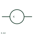
IEEE-oriented graphical reference for ac relay coil, with public vendor evidence and drawing-reading notes.
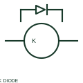
IEEE-oriented graphical reference for relay coil with diode suppression, with public vendor evidence and drawing-reading notes.
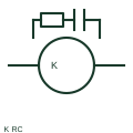
IEEE-oriented graphical reference for relay coil with rc suppression, with public vendor evidence and drawing-reading notes.
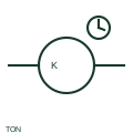
IEEE-oriented graphical reference for on-delay timer relay, with public vendor evidence and drawing-reading notes.
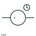
IEEE-oriented graphical reference for off-delay timer relay, with public vendor evidence and drawing-reading notes.
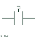
IEEE-oriented graphical reference for maintained normally-open contact, with public vendor evidence and drawing-reading notes.
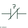
IEEE-oriented graphical reference for maintained normally-closed contact, with public vendor evidence and drawing-reading notes.
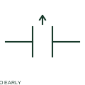
IEEE-oriented graphical reference for early-make normally-open contact, with public vendor evidence and drawing-reading notes.
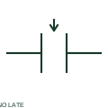
IEEE-oriented graphical reference for late-make normally-open contact, with public vendor evidence and drawing-reading notes.
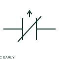
IEEE-oriented graphical reference for early-break normally-closed contact, with public vendor evidence and drawing-reading notes.
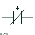
IEEE-oriented graphical reference for late-break normally-closed contact, with public vendor evidence and drawing-reading notes.
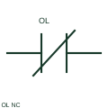
IEEE-oriented graphical reference for motor overload trip nc contact, with public vendor evidence and drawing-reading notes.
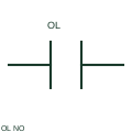
IEEE-oriented graphical reference for motor overload alarm no contact, with public vendor evidence and drawing-reading notes.
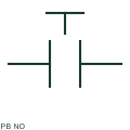
IEEE-oriented graphical reference for normally open pushbutton, with public vendor evidence and drawing-reading notes.
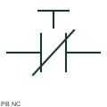
IEEE-oriented graphical reference for normally closed pushbutton, with public vendor evidence and drawing-reading notes.
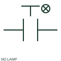
IEEE-oriented graphical reference for illuminated normally-open pushbutton, with public vendor evidence and drawing-reading notes.
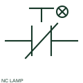
IEEE-oriented graphical reference for illuminated normally-closed pushbutton, with public vendor evidence and drawing-reading notes.
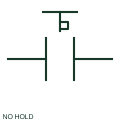
IEEE-oriented graphical reference for maintained normally-open pushbutton, with public vendor evidence and drawing-reading notes.

IEEE-oriented graphical reference for maintained normally-closed pushbutton, with public vendor evidence and drawing-reading notes.
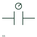
IEEE-oriented graphical reference for selector switch, with public vendor evidence and drawing-reading notes.
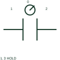
IEEE-oriented graphical reference for three-position maintained selector, with public vendor evidence and drawing-reading notes.
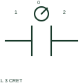
IEEE-oriented graphical reference for three-position centre-return selector, with public vendor evidence and drawing-reading notes.
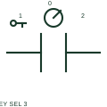
IEEE-oriented graphical reference for three-position key selector, with public vendor evidence and drawing-reading notes.
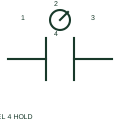
IEEE-oriented graphical reference for four-position maintained selector, with public vendor evidence and drawing-reading notes.
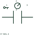
IEEE-oriented graphical reference for four-position key selector, with public vendor evidence and drawing-reading notes.
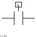
IEEE-oriented graphical reference for normally-open limit switch, with public vendor evidence and drawing-reading notes.
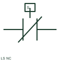
IEEE-oriented graphical reference for normally-closed limit switch, with public vendor evidence and drawing-reading notes.
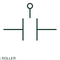
IEEE-oriented graphical reference for roller-operated limit switch, with public vendor evidence and drawing-reading notes.
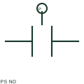
IEEE-oriented graphical reference for pressure switch no, with public vendor evidence and drawing-reading notes.
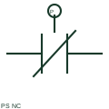
IEEE-oriented graphical reference for pressure switch nc, with public vendor evidence and drawing-reading notes.
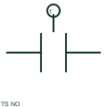
IEEE-oriented graphical reference for temperature switch no, with public vendor evidence and drawing-reading notes.
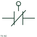
IEEE-oriented graphical reference for temperature switch nc, with public vendor evidence and drawing-reading notes.
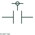
IEEE-oriented graphical reference for float level switch no, with public vendor evidence and drawing-reading notes.
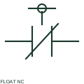
IEEE-oriented graphical reference for float level switch nc, with public vendor evidence and drawing-reading notes.
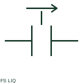
IEEE-oriented graphical reference for liquid flow switch, with public vendor evidence and drawing-reading notes.
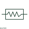
IEEE-oriented graphical reference for heating element, with public vendor evidence and drawing-reading notes.
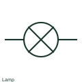
IEEE-oriented graphical reference for indicator lamp, with public vendor evidence and drawing-reading notes.

IEEE-oriented graphical reference for transformer-fed indicator lamp, with public vendor evidence and drawing-reading notes.
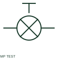
IEEE-oriented graphical reference for push-to-test indicator lamp, with public vendor evidence and drawing-reading notes.
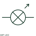
IEEE-oriented graphical reference for led indicator lamp, with public vendor evidence and drawing-reading notes.
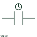
IEEE-oriented graphical reference for on-delay normally-open contact, with public vendor evidence and drawing-reading notes.
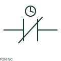
IEEE-oriented graphical reference for on-delay normally-closed contact, with public vendor evidence and drawing-reading notes.
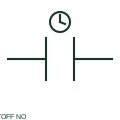
IEEE-oriented graphical reference for off-delay normally-open contact, with public vendor evidence and drawing-reading notes.
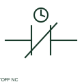
IEEE-oriented graphical reference for off-delay normally-closed contact, with public vendor evidence and drawing-reading notes.
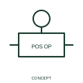
A positive-operation qualifier identifies the documented mechanically imposed operating direction.
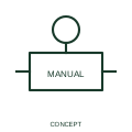
This qualifier identifies an operator action applied to the associated mechanism.
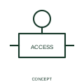
This qualifier indicates that manual access to the operating mechanism is protected or restricted.
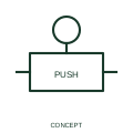
A pushbutton qualifier identifies the actuation method of a contact or device.
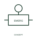
An emergency-operation qualifier marks the documented emergency actuation role.
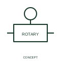
This qualifier identifies an operating mechanism actuated by rotation.
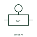
A key-operation qualifier identifies a mechanism requiring the specified key action.
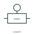
This qualifier identifies actuation by a foot-operated mechanism.
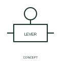
A lever-operation qualifier identifies a manually moved lever mechanism.
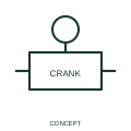
This qualifier identifies manual operation through a crank mechanism.
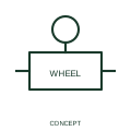
A handwheel qualifier identifies an operating mechanism moved by a wheel.
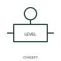
This qualifier identifies actuation responding to liquid level.
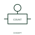
This qualifier identifies operation related to a count of events.
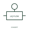
A liquid-flow qualifier identifies the process input operating a device.
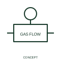
A gas-flow qualifier identifies operation responding to gas movement.
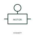
This qualifier identifies an operating mechanism driven by a motor.
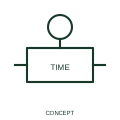
A timed-operation qualifier identifies operation influenced by the documented timing function.
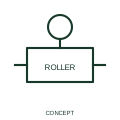
This qualifier identifies contact with a roller-operated mechanism.
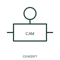
This qualifier identifies operation by a cam mechanism.
A cam-profile indication describes the mechanical profile associated with an operating sequence.
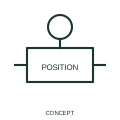
This qualifier marks the publisher's switch-position function element.
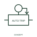
An automatic-trip qualifier indicates that the associated mechanism can operate automatically under its documented condition.
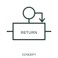
A spring-return qualifier indicates return after the specified operating force is removed.
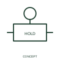
A maintained-position qualifier indicates that the operating position remains after actuation.
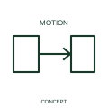
A linear-motion qualifier identifies movement or force in one documented direction.
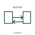
This qualifier identifies motion or force in both directions along a linear path.
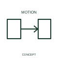
A transition indication identifies a documented change between positions or states.
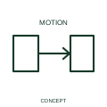
A rotary-motion qualifier identifies movement or torque in one direction of rotation.
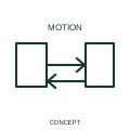
This qualifier identifies a mechanism capable of rotary movement in either direction.
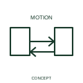
This qualifier identifies rotary movement in both directions over a limited travel.
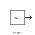
A thermal-effect qualifier identifies a function responding to or producing heat-related behaviour.
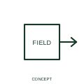
This qualifier identifies a function involving a magnetic effect.
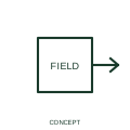
A magnetostrictive qualifier identifies a function using the relationship between magnetisation and mechanical deformation.
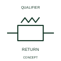
This indication identifies the automatic return behaviour of a mechanical control relationship.
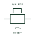
A stop-latch indication identifies a mechanically retained control position.
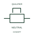
This form identifies the neutral state of the represented stop-latch mechanism.
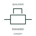
This form identifies an engaged stop-latch mechanism.
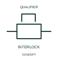
A mechanical interlock indication links devices whose movements are constrained by a physical relationship.
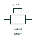
This form identifies the publisher's two-way latching-device arrangement.
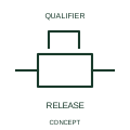
This qualifier identifies release of a latching mechanism by manual action.
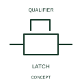
This form identifies a two-way latch using a documented key operation.
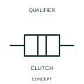
A clutch qualifier identifies a selectively coupled mechanical relationship.
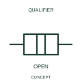
This indication identifies the disconnected state of a mechanical coupling.
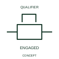
This indication identifies engagement between the represented mechanical elements.
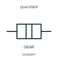
A gear-connection indication identifies transmission through a gearing relationship.
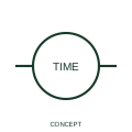
A clock indication identifies a time display or clock function in the circuit documentation.
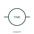
This representation identifies the publisher's normally-open clock contact that closes every minute.
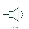
A bell indication identifies an audible annunciation output in a control circuit.
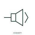
A buzzer indication identifies the specified audible signalling output.
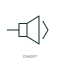
A siren indication identifies an audible alarm output with the documented operating role.
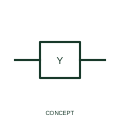
This representation identifies the electrical actuator associated with a solenoid-operated valve.
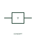
This representation identifies the publisher's open-valve closing function associated with solenoid operation.
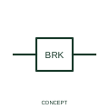
This representation identifies an electromagnetic brake actuated through its documented electrical circuit.
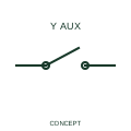
This form identifies a normally-open auxiliary contact associated with a solenoid valve.
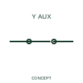
This form identifies a normally-closed auxiliary contact associated with a solenoid valve.
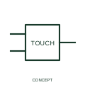
A touch-switch representation identifies operation by the documented touch-sensing mechanism.
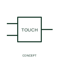
This form identifies a normally-open touch-switch output.
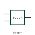
This form identifies a normally-closed touch-switch output.
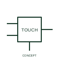
This representation distinguishes a separately supplied three-wire touch-switch interface.
This representation distinguishes a pull-cord actuator whose operated state is latched.
This representation distinguishes a foot actuator with a retained operated state.
This representation distinguishes a lever actuator with a maintained or latched operated state.