AND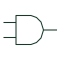
AND gate
A logic element whose output is true when all stated positive-logic inputs are true.
Schematic
Logic gates, signal processing and analogue functions used in control, automation and electronic diagrams. Explore 63 references, with original explanations and public primary sources.
A logic element whose output is true when all stated positive-logic inputs are true.
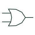
A positive-logic element whose output is true when at least one input is true.
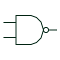
A logic gate that inverts the result of an AND operation.
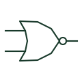
A logic gate that inverts an inclusive-OR result.
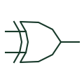
For two positive-logic inputs, produces a true output when the input states differ.
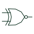
For two positive-logic inputs, produces a true output when the input states are equal.
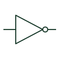
Produces the opposite logical state of its defined digital input.
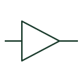
Transfers a digital state through a non-inverting logic output stage.
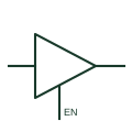
A digital output stage that can drive logical states or enter its documented high-impedance state.
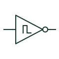
A digital inverter with hysteresis between its input switching thresholds.
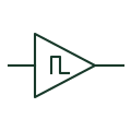
A non-inverting digital element with separate rising and falling input thresholds.
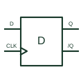
Captures its data input at the documented positive clock edge and retains that digital state.
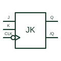
Updates or toggles its stored state from J and K inputs at the selected negative clock edge.
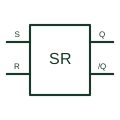
Retains a digital state that is changed by the defined set or reset input conditions.
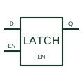
Follows the input data while its latch-enable condition is active and retains it when that condition ends.
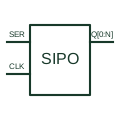
Shifts serial input data through storage stages to parallel outputs at the documented clock events.
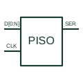
Loads a parallel word and presents its bits through a serial shift output.
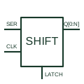
Combines a serial shift path with a separate output-storage stage.
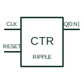
Counts clock events through cascaded storage stages whose output changes do not occur simultaneously.
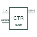
Updates its binary count from a common clock with the documented count-enable, load and clear controls.
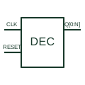
Advances a decoded output sequence through the documented ten-state counter arrangement.
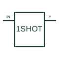
Produces a timed output pulse that can be extended by a qualifying retrigger condition.
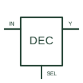
Uses binary selection and enable conditions to activate the documented selected output.
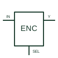
Encodes the highest-priority qualifying input into the specified binary output word.
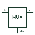
Selects one of several digital inputs for the documented output according to its selection controls.
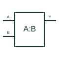
Compares two digital words to provide the specified equality and magnitude indications.
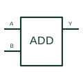
Adds binary input words with the documented carry-in and produces sum and carry outputs.
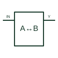
Drives data between two digital buses according to the selected direction and enable conditions.
Transfers digital information between the documented logic-voltage domains.
Provides a logic output through a transistor pull-down stage requiring the documented external load or pull-up.
Computes a parity indication from the defined digital input word.
Controls an oscillator through a phase-comparison feedback arrangement to follow the documented reference.
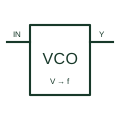
Generates an oscillating output whose frequency responds to the documented control voltage.
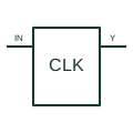
Provides the documented clock signal or signals used by digital circuitry.
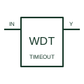
Supervises a qualifying activity signal and operates its output when the documented watchdog timing condition is violated.
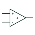
An analogue amplifier represented by inverting and non-inverting inputs, an output and its supply connections.
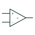
Compares two analogue input voltages and produces the documented output-state indication.
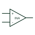
Amplifies a differential input signal using an instrumentation-amplifier input and gain arrangement.
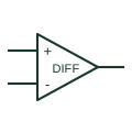
Produces an analogue output related to the difference between two input signals with the documented gain/reference arrangement.
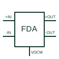
Processes an analogue input to provide two complementary output signals around a defined common-mode level.
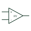
Amplifies a voltage associated with a current-sensing shunt using the selected measurement-input arrangement.
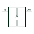
Transfers an analogue measurement across the documented electrical isolation boundary.
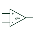
Produces an output current controlled by its differential input voltage and documented bias arrangement.
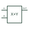
Produces an analogue output related to the product of two input quantities and the selected scaling/summing arrangement.
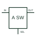
Connects or disconnects an analogue signal path under its documented digital control.
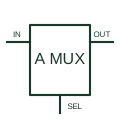
Selects a continuous-signal channel through the documented controlled switching arrangement.
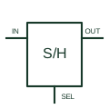
Acquires an analogue signal during the documented sampling interval and retains a representation during hold.
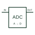
Converts a sampled analogue quantity into the selected digital representation.
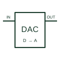
Converts a digital code into the documented analogue output quantity.
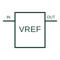
Provides a reference voltage through a series-connected supply and output arrangement.
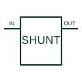
Establishes a reference voltage using a shunt-current path and the documented bias or feedback circuit.
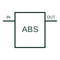
Uses an active amplifier/diode arrangement to rectify a signal according to the documented circuit.
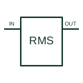
Produces a DC output related to the RMS value of its input signal under the selected implementation.
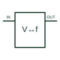
Converts between an analogue voltage and a pulse-frequency representation in the documented selected configuration.
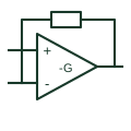
Uses an amplifier feedback connection that produces the documented inverted signal relationship.
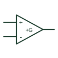
Uses an amplifier feedback arrangement to amplify a signal without the intended polarity inversion.
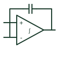
Uses a documented amplifier/capacitor feedback arrangement to obtain an integrating signal response.
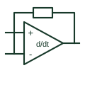
Uses an amplifier input/feedback arrangement to obtain a differentiating response over its intended operating band.
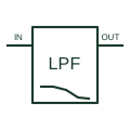
Passes the intended lower-frequency signal content while attenuating higher-frequency content through an active filter circuit.
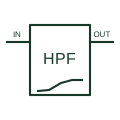
Attenuates lower-frequency content while passing the intended higher-frequency signal band.
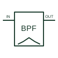
Passes an intended frequency band while attenuating content below and above that band.

Attenuates a defined frequency region while retaining the intended content outside it.
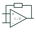
Converts an input current into an output voltage through the documented feedback arrangement.